

Lab 26 – Virtual router and firewall between VLANs: MikroTik CHR (OPNsense as an alternative)
Dependencies
Section titled “Dependencies”- Previous labs:
- Nodes:
desopve01(where the router runs),desopve02anddesopve03(where the test containers run). - Test containers:
- CT 121
vlan-ct1ondesopve01and CT 122vlan-ct2ondesopve02, VLAN 10; - CT 123
vlan-ct3ondesopve03, VLAN 20; - all on
vmbr1, withiperf3andtcpdump.
- CT 121
- Software: raw image of MikroTik Cloud Hosted Router (CHR) 7.25.1, downloaded from the MikroTik website through the proxy: the lab proxy must allow
download.mikrotik.com. - Services: DNS on the DC (172.27.199.20), proxy
proxy.proxmox.community:3128. - Router address on the management network: 172.27.199.26 (
router01.proxmox.community). - Credentials:
root/<lab-password>on the nodes,admin/<lab-password>on the router → Appendix B.
Objectives
Section titled “Objectives”- A router VM,
router01(MikroTik CHR), created from a ready-made disk image, with a single trunk device that receives only VLANs 10 and 20:bridge vlan showconfirms it. - Routing between VLAN 10 and VLAN 20 through the router, with DHCP, NAT toward the lab network and a firewall that blocks VLAN 20 → VLAN 10, checked with
ping,tcpdumpand the rule counters. - Knowing what stops working when the router is down, and how long it took in this lab to route again after a start.
- Knowing how much routed traffic the free CHR license lets through, how to measure it, and when OPNsense is the better choice.
How it works
Section titled “How it works”Router-on-a-stick
Section titled “Router-on-a-stick”In lab 20 the guests in VLAN 10 and VLAN 20 were isolated: the bridge does not route, it separates. To let them talk you need a router with a leg in each VLAN. Instead of giving it one network device per VLAN, you give it a single trunk device: frames arrive with their 802.1Q tag and the router creates a logical interface for each VLAN. This is the classic router-on-a-stick configuration.
flowchart LR
    subgraph N1["desopve01"]
        R["VM 261 router01<br/>ether1 172.27.199.26<br/>ether2 trunk 10,20"]
        C1["CT 121<br/>VLAN 10"]
    end
    subgraph N2["desopve02"]
        C2["CT 122<br/>VLAN 10"]
    end
    subgraph N3["desopve03"]
        C3["CT 123<br/>VLAN 20"]
    end
    R -- "vmbr0, untagged" --- LAB["lab network 172.27.199.0/24<br/>DC, proxy, rtr-core"]
    R -- "vmbr1 trunk (10, 20)" --- SW["trunk between the nodes<br/>bond0 on every node"]
    C1 -- "tag 10" --- SW
    C2 -- "tag 10" --- SW
    C3 -- "tag 20" --- SW
trunks and the bridge VLAN filter
Section titled “trunks and the bridge VLAN filter”A VM network device on a VLAN-aware bridge without tag and without trunks sits untagged in VLAN 1 (PVID), but Proxmox VE also adds it, tagged, to all the VLANs in bridge-vids (2-4094, see Lab 20). With the option trunks=10;20 the port stays untagged in VLAN 1 and receives, tagged, only VLANs 10 and 20: the router receives both of them, and no others. The option is set from the command line (qm set): the GUI dialog only has the VLAN Tag field.
NAT and firewall on the router
Section titled “NAT and firewall on the router”- NAT: the router goes out to the lab network with its own address (masquerading). The DC, the proxy and
rtr-coredo not need to know about the 10.10.10.0/24 and 10.20.20.0/24 networks. - Stateful firewall: RouterOS has two main chains.
inputprotects the router itself,forwarddecides what passes through the router. Theestablished,relatedrule lets through the replies to connections that were already allowed: you only need to authorize whoever opens the connection.
In this lab the policy is:
| From → to | Allowed |
|---|---|
| VLAN 10 → anywhere | yes |
| VLAN 20 → lab network (DC, proxy) | yes |
| VLAN 20 → VLAN 10 | no, except replies to connections opened from VLAN 10 |
| Lab network → router (SSH) | yes, only from 172.27.199.0/24 |
CHR licensing
Section titled “CHR licensing”CHR can be downloaded and used for free. According to MikroTik’s documentation, the free license limits every interface to 1 Mbit/s of outbound (upload) traffic and leaves the other features unrestricted. With an account on mikrotik.com you can request a 60-day trial of the paid levels (P1 at 1 Gbit/s, P10 at 10 Gbit/s, P-Unlimited with no limit); in production you buy a perpetual license. The free license is enough to learn the configuration; the bandwidth test in the verification shows what it means for routed traffic.
OPNsense as an alternative
Section titled “OPNsense as an alternative”The same design (router-on-a-stick, DHCP, NAT, firewall) can be built with OPNsense, an open source firewall based on FreeBSD. It was not installed in this lab; the comparison sums up the differences that matter on Proxmox VE.
| Aspect | MikroTik CHR | OPNsense |
|---|---|---|
| Installation | ready-made disk image to import (128 MiB) | ISO with installer |
| Resources | in the lab: 1 vCPU, 512 MiB of RAM | at least 3 GB of RAM and a dual-core CPU, according to the OPNsense documentation |
| Management | CLI, WinBox, web interface | full web interface |
| License | free, limited to 1 Mbit/s per interface; 60-day trial; paid licenses | open source, no limits |
| Security features | firewall, VPN, dynamic routing | firewall, VPN, IDS/IPS (Suricata), proxy, plugins |
| VirtIO NICs | supported | supported (vtnet); on virtual machines the documentation recommends disabling all hardware offloading in Interfaces → Settings |
| Guest agent | built in | os-qemu-guest-agent plugin |
For learning routing and VLANs, CHR is lighter and quicker to set up; for a perimeter firewall with a graphical interface and advanced security features, OPNsense is the more common choice.
Test environment and versions
Section titled “Test environment and versions”The outputs and measurements in this lab come from tests run in November 2026 with this configuration:
| Component | Configuration used |
|---|---|
| Proxmox VE | 9.2.26, kernel 7.0.14-28-pve (Lab 04) |
| Router | RouterOS CHR 7.25.1, license level free; VM 261 on desopve01 with 1 vCPU, 512 MiB of RAM, two VirtIO network devices and its disk on rbd-vm (Ceph 20.2, Lab 17) |
| Network | VLAN-aware vmbr1 on bond0, active-backup on 10 GbE ports, MTU 1500 (Lab 21); trunk device with trunks=10;20 |
| Test guests | CT 121 (desopve01) and CT 122 (desopve02) in VLAN 10, CT 123 (desopve03) in VLAN 20, from the Debian 13 template, with iperf3 (Lab 20) |
| Bandwidth tests | iperf3 with one TCP flow and default options: 8 s through the router (CT 121 → CT 123), 5 s within VLAN 10 (CT 121 → CT 122) |
What the tests measure, and what they do not. The outputs show one run of each test. The router was stopped with a clean shutdown (qm shutdown), not by a crash or a node failure. During the bandwidth test, neither the CPU load of the router nor its interface counters were recorded.
Procedure
Section titled “Procedure”1. Download the image into the import storage
Section titled “1. Download the image into the import storage”-
On node
desopve01, download the CHR raw image into theimportfolder of thelocalstorage and unzip it:root@desopve01 cd /var/lib/vz/importexport https_proxy=http://proxy.proxmox.community:3128curl -s https://download.mikrotik.com/routeros/NEWESTa7.stableOutput 7.25.1 1793623193root@desopve01:/var/lib/vz/import curl -s -O https://download.mikrotik.com/routeros/7.25.1/chr-7.25.1.img.zipunzip chr-7.25.1.img.zipOutput Archive: chr-7.25.1.img.zipinflating: chr-7.25.1.img -
In the import storage, Proxmox VE lists only the files with an extension it recognizes, such as
.raw,.qcow2,.vmdkor.ova. An.imgfile does not show up: rename it to.raw, which is the same format:root@desopve01:/var/lib/vz/import pvesm list local --content importOutput Volid Format Type Size VMIDlocal:import/debian-13-genericcloud-amd64.qcow2 qcow2 import 341180416root@desopve01:/var/lib/vz/import mv chr-7.25.1.img chr-7.25.1.raw && rm chr-7.25.1.img.zippvesm list local --content importOutput Volid Format Type Size VMIDlocal:import/debian-13-genericcloud-amd64.qcow2 qcow2 import 341180416local:import/chr-7.25.1.raw raw import 134217728
2. Create the VM with the imported disk
Section titled “2. Create the VM with the imported disk”-
Create VM on
desopve01:- General: VM ID
261, namerouter01; - OS: Do not use any media;
- System: default values, with Qemu Agent enabled: RouterOS CHR includes the guest agent.
- General: VM ID
-
Disks: delete the proposed disk (
scsi0, trash can icon) and click Import. In the new disk set Bus/DeviceSCSI 0, Import Storagelocal, Select Imagechr-7.25.1.raw, Target Storagerbd-vm. With its disk on Ceph, the router can be migrated between nodes.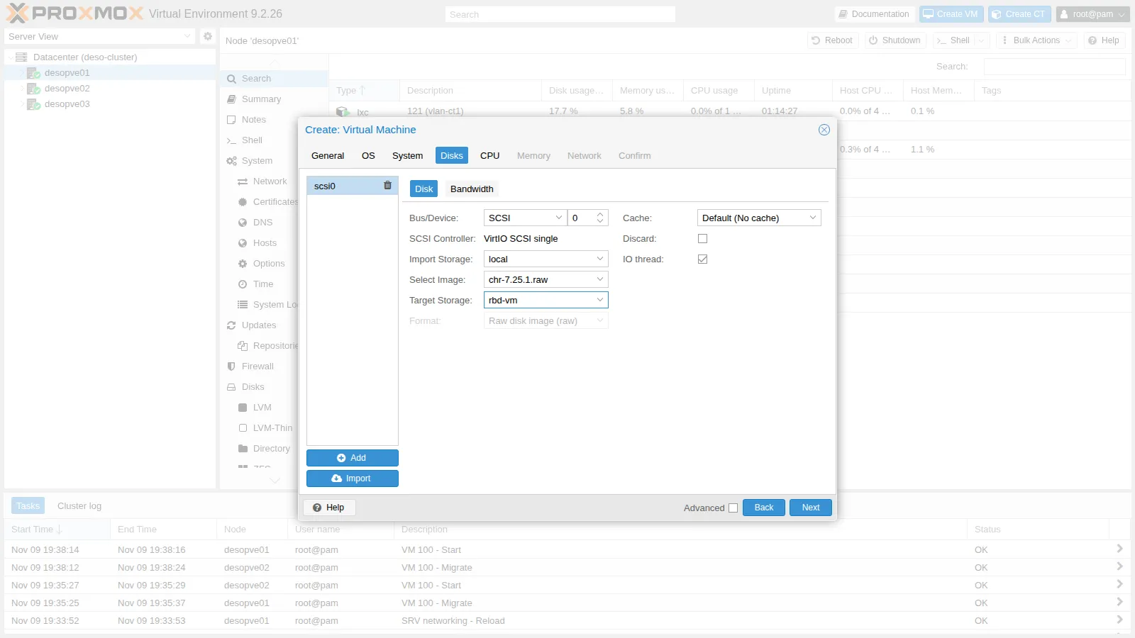
-
CPU 1 core, Memory 512 MiB, Network
vmbr0with the VirtIO model: it will beether1, the uplink to the lab network. In the summary the disk appears asrbd-vm:0,import-from=local:import/chr-7.25.1.raw: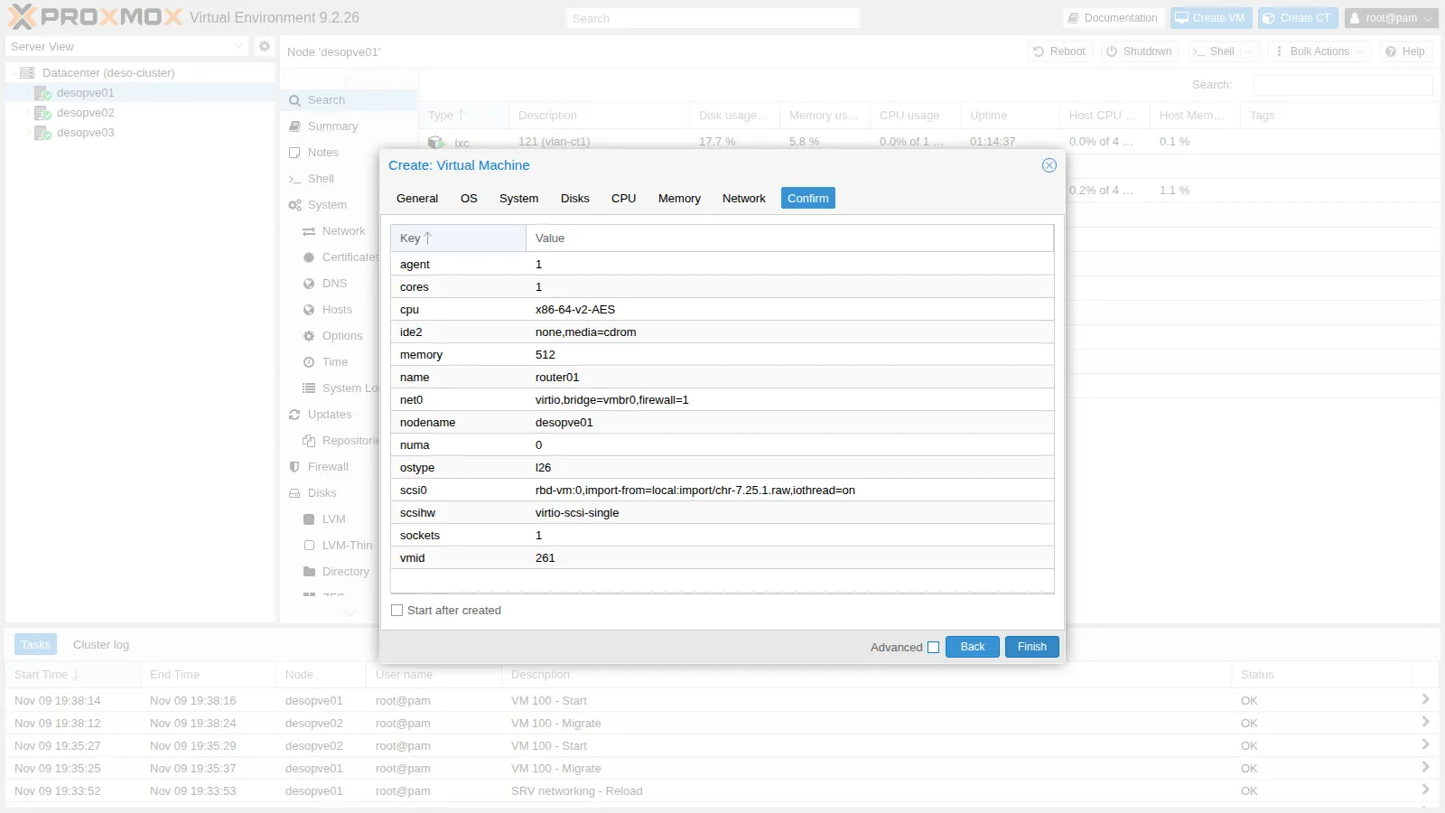
Click Finish without starting the VM.
3. The trunk device
Section titled “3. The trunk device”-
Add the second network device on
vmbr1with only VLANs 10 and 20, remove the unneeded CD drive and make the router start with the node:root@desopve01 qm set 261 --net1 virtio,bridge=vmbr1,trunks='10;20' --boot order=scsi0 --delete ide2 --onboot 1Output update VM 261: -boot order=scsi0 -delete ide2 -net1 virtio,bridge=vmbr1,trunks=10;20 -onboot 1root@desopve01 qm start 261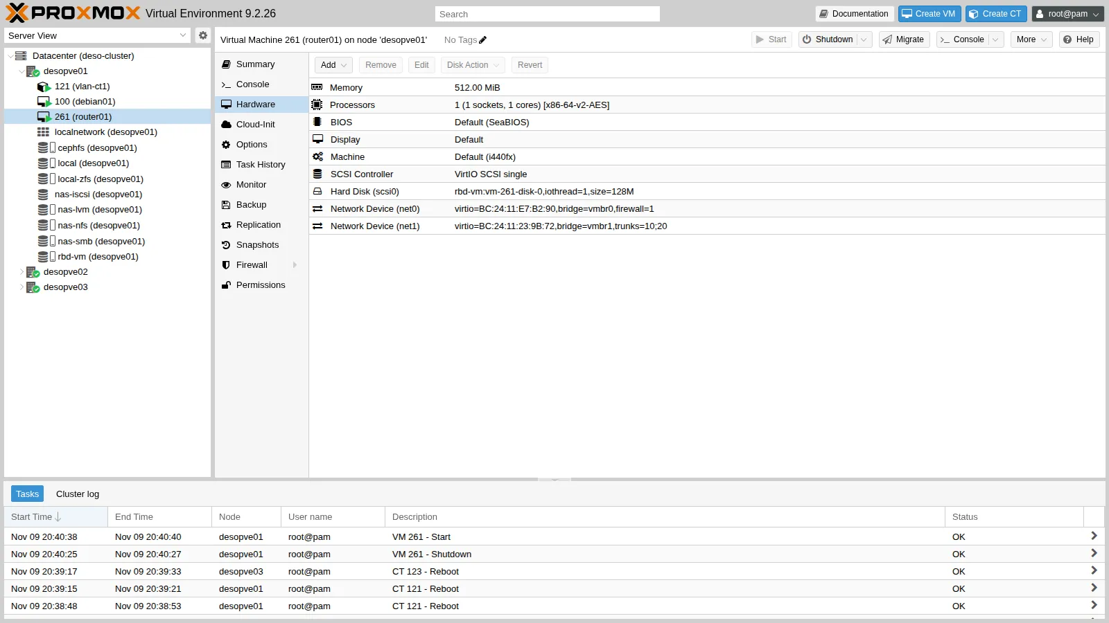
-
With the VM running, the bridge VLAN filter shows what enters the port of the second network device (
tap261i1): VLANs 10 and 20 tagged, plus the untagged PVID 1 that the bridge assigns by default:root@desopve01 bridge vlan show dev tap261i1Output port vlan-idtap261i1 1 PVID Egress Untagged1020
4. First login from the console
Section titled “4. First login from the console”-
Open Console on the VM. At the
CHR Login:prompt log in asadminwith an empty password, answernto the license question and set the new password (<lab-password>). Then give the router its name, the management address onether1, the gateway and the DNS server:/system identity set name=router01/ip address add address=172.27.199.26/24 interface=ether1/ip route add gateway=172.27.199.1/ip dns set servers=172.27.199.20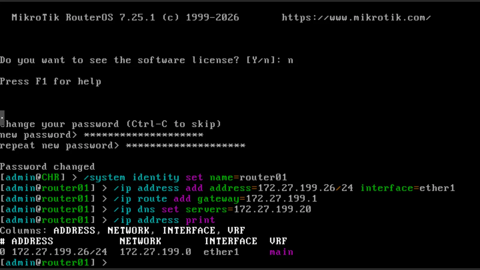
-
From the DC, register the router’s name in DNS (A and PTR records):
PowerShell — desopve-dc01 Add-DnsServerResourceRecordA -ZoneName proxmox.community -Name router01 -IPv4Address 172.27.199.26 -CreatePtr -
From here on you work over SSH (
ssh [email protected]). The interfaces appear in the order of the VM’s network devices:ether1isnet0(vmbr0),ether2isnet1(the trunk). The MACs match those in Proxmox:RouterOS — router01 /interface ethernet printOutput Flags: R - RUNNINGColumns: NAME, MTU, MAC-ADDRESS, ARP# NAME MTU MAC-ADDRESS ARP0 R ether1 1500 BC:24:11:E7:B2:90 enabled1 R ether2 1500 BC:24:11:23:9B:72 enabled
5. VLANs and addresses
Section titled “5. VLANs and addresses”-
Create a VLAN interface for each network on the trunk and group the interfaces into two lists,
LANandWAN, which the firewall will use:/interface vlan add name=vlan10 vlan-id=10 interface=ether2 comment="VLAN 10 sul trunk"/interface vlan add name=vlan20 vlan-id=20 interface=ether2 comment="VLAN 20 sul trunk"/interface list add name=LAN/interface list add name=WAN/interface list member add list=WAN interface=ether1/interface list member add list=LAN interface=vlan10/interface list member add list=LAN interface=vlan20/ip address add address=10.10.10.1/24 interface=vlan10/ip address add address=10.20.20.1/24 interface=vlan20 -
Check:
RouterOS — router01 /interface print where type~"ether|vlan"Output Flags: R - RUNNINGColumns: NAME, TYPE, ACTUAL-MTU, MAC-ADDRESS# NAME TYPE ACTUAL-MTU MAC-ADDRESS0 R ether1 ether 1500 BC:24:11:E7:B2:901 R ether2 ether 1500 BC:24:11:23:9B:72;;; VLAN 10 sul trunk2 R vlan10 vlan 1500 BC:24:11:23:9B:72;;; VLAN 20 sul trunk3 R vlan20 vlan 1500 BC:24:11:23:9B:72RouterOS — router01 /ip address printOutput Columns: ADDRESS, NETWORK, INTERFACE, VRF# ADDRESS NETWORK INTERFACE VRF0 172.27.199.26/24 172.27.199.0 ether1 main1 10.10.10.1/24 10.10.10.0 vlan10 main2 10.20.20.1/24 10.20.20.0 vlan20 main
6. DHCP for each VLAN
Section titled “6. DHCP for each VLAN”-
One address pool and one DHCP server per VLAN; in the DHCP network the gateway is the router and the DNS server is the DC:
/ip pool add name=pool-vlan10 ranges=10.10.10.150-10.10.10.199/ip pool add name=pool-vlan20 ranges=10.20.20.150-10.20.20.199/ip dhcp-server add name=dhcp-vlan10 interface=vlan10 address-pool=pool-vlan10 lease-time=1h/ip dhcp-server add name=dhcp-vlan20 interface=vlan20 address-pool=pool-vlan20 lease-time=1h/ip dhcp-server network add address=10.10.10.0/24 gateway=10.10.10.1 dns-server=172.27.199.20 domain=proxmox.community/ip dhcp-server network add address=10.20.20.0/24 gateway=10.20.20.1 dns-server=172.27.199.20 domain=proxmox.community -
Check:
RouterOS — router01 /ip dhcp-server printOutput Columns: NAME, INTERFACE, ADDRESS-POOL, LEASE-TIME# NAME INTERFACE ADDRESS-POOL LEASE-TIME0 dhcp-vlan10 vlan10 pool-vlan10 1h1 dhcp-vlan20 vlan20 pool-vlan20 1hRouterOS — router01 /ip dhcp-server network printOutput Columns: ADDRESS, GATEWAY, DNS-SERVER, DOMAIN# ADDRESS GATEWAY DNS-SERVER DOMAIN0 10.10.10.0/24 10.10.10.1 172.27.199.20 proxmox.community1 10.20.20.0/24 10.20.20.1 172.27.199.20 proxmox.community
7. NAT and firewall
Section titled “7. NAT and firewall”-
NAT toward the lab network:
/ip firewall nat add chain=srcnat out-interface-list=WAN action=masquerade comment="NAT verso la rete del lab" -
The firewall rules, in the order in which they are evaluated. The rule that allows SSH from the lab network comes before the final
dropof theinputchain: the current SSH session stays open thanks to the first rule (established,related)./ip firewall filter add chain=input action=accept connection-state=established,related comment="input: risposte"/ip firewall filter add chain=input action=drop connection-state=invalid comment="input: pacchetti non validi"/ip firewall filter add chain=input action=accept protocol=icmp comment="input: ping"/ip firewall filter add chain=input action=accept in-interface-list=LAN protocol=udp dst-port=67 comment="input: DHCP dalle VLAN"/ip firewall filter add chain=input action=accept in-interface=ether1 src-address=172.27.199.0/24 protocol=tcp dst-port=22 comment="input: SSH solo dalla rete del lab"/ip firewall filter add chain=input action=drop comment="input: tutto il resto"/ip firewall filter add chain=forward action=accept connection-state=established,related comment="forward: risposte"/ip firewall filter add chain=forward action=drop connection-state=invalid comment="forward: pacchetti non validi"/ip firewall filter add chain=forward action=accept in-interface=vlan10 comment="forward: VLAN 10 verso tutti"/ip firewall filter add chain=forward action=accept in-interface=vlan20 out-interface-list=WAN comment="forward: VLAN 20 solo verso la rete del lab"/ip firewall filter add chain=forward action=drop comment="forward: tutto il resto"
8. The containers use the router
Section titled “8. The containers use the router”-
CT 121, from the GUI: container 121 → Network →
net0→ Edit → IPv4: DHCP. The VLAN 10 tag stays as it is.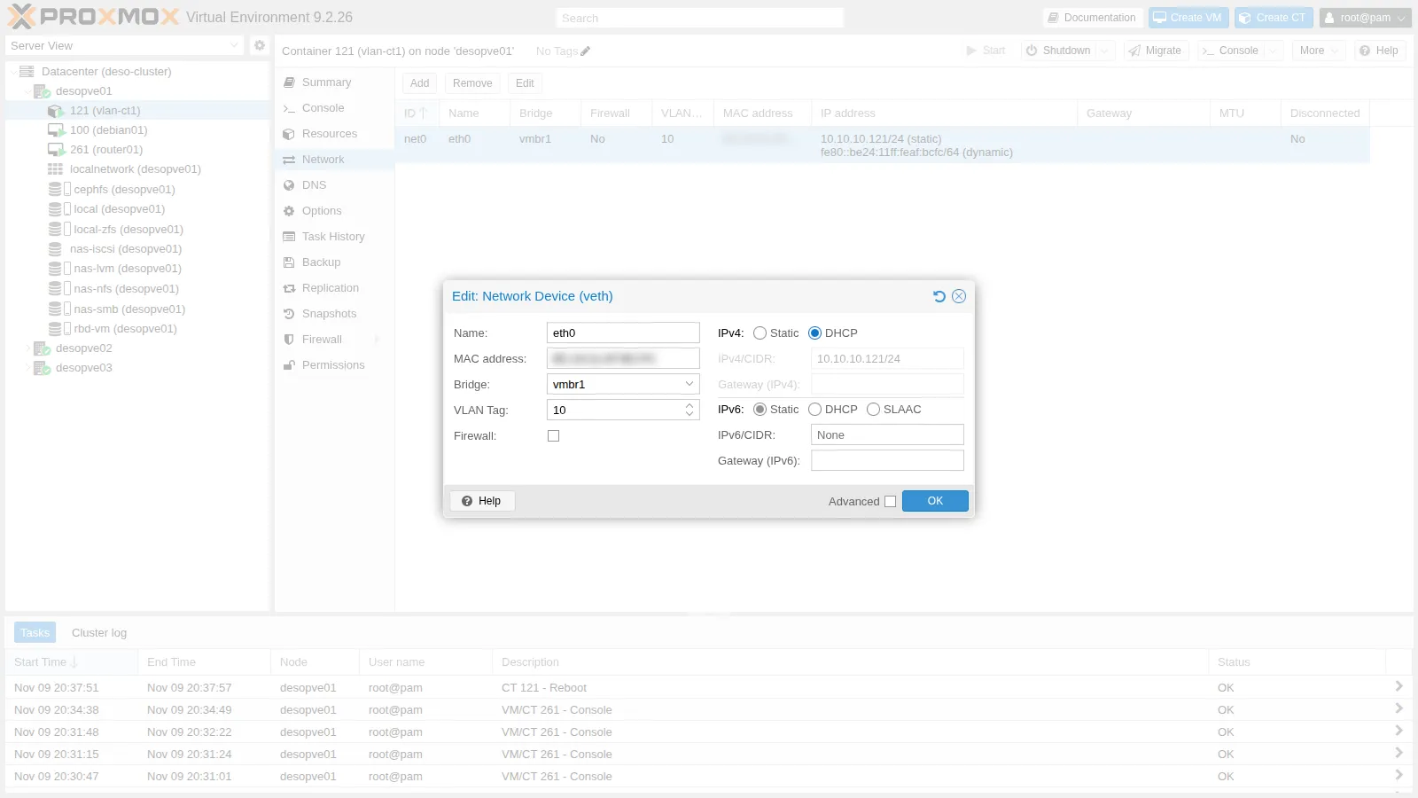
-
After the container restarts, the router assigns it the first free address in the pool, starting from the top, together with the gateway and the DNS server:
root@desopve01 pct reboot 121pct exec 121 -- ip routeOutput default via 10.10.10.1 dev eth010.10.10.0/24 dev eth0 proto kernel scope link src 10.10.10.199root@desopve01 pct exec 121 -- cat /etc/resolv.confOutput domain proxmox.communitysearch proxmox.communitynameserver 172.27.199.20RouterOS — router01 /ip dhcp-server lease printOutput Flags: D - DYNAMICColumns: ADDRESS, MAC-ADDRESS, HOST-NAME, SERVER, STATUS, LAST-SEEN# ADDRESS MAC-ADDRESS HOST-NAME SERVER STATUS LAST-SEEN0 D 10.10.10.199 BC:24:11:AF:BC:FC vlan-ct1 dhcp-vlan10 bound 5s -
Servers are better off with a fixed address even with DHCP: make the lease static and assign it the desired address. For CT 123 the static lease is created in advance, from the container’s MAC. The MACs of your containers differ from those in the examples: read them with
pct config 121 | grep hwaddr(and the same for 122 and 123) and put them in place of the placeholders:/ip dhcp-server lease make-static [find mac-address=<MAC del CT 121>]/ip dhcp-server lease set [find mac-address=<MAC del CT 121>] address=10.10.10.121 comment="vlan-ct1 (CT 121)"/ip dhcp-server lease add server=dhcp-vlan20 mac-address=<MAC del CT 123> address=10.20.20.123 comment="vlan-ct3 (CT 123)" -
CT 123 switches to DHCP from the command line; CT 122 keeps its static address, but with the router as its gateway. In
pct setrepeat the current MAC (hwaddr), otherwise Proxmox generates a new one:root@desopve03 pct set 123 -net0 name=eth0,bridge=vmbr1,hwaddr=<MAC del CT 123>,ip=dhcp,tag=20,type=vethpct reboot 123root@desopve02 pct set 122 -net0 name=eth0,bridge=vmbr1,hwaddr=<MAC del CT 122>,ip=10.10.10.122/24,gw=10.10.10.1,tag=10,type=vethAfter restarting CT 121 and CT 123:
RouterOS — router01 /ip dhcp-server lease printOutput Columns: ADDRESS, MAC-ADDRESS, HOST-NAME, SERVER, STATUS, LAST-SEEN# ADDRESS MAC-ADDRESS HOST-NAME SERVER STATUS LAST-SEEN;;; vlan-ct1 (CT 121)0 10.10.10.121 BC:24:11:AF:BC:FC vlan-ct1 dhcp-vlan10 bound 17s;;; vlan-ct3 (CT 123)1 10.20.20.123 BC:24:11:F4:8A:80 vlan-ct3 dhcp-vlan20 bound 5s
9. The RouterOS guest agent
Section titled “9. The RouterOS guest agent”The CHR guest agent reports the router’s addresses to Proxmox VE: they appear in the VM’s Summary and can be read from the command line:
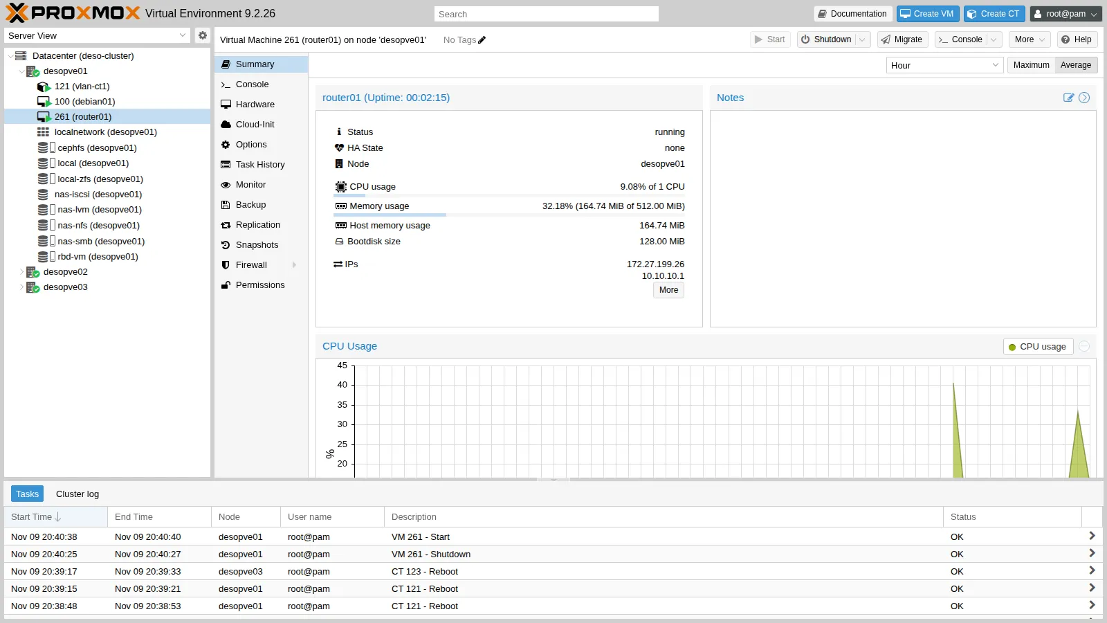
qm guest cmd 261 network-get-interfaces | python3 -c "import sys,json; [print(i['name'], [a['ip-address'] for a in i.get('ip-addresses',[]) if a['ip-address-type']=='ipv4']) for i in json.load(sys.stdin)]"ether1 ['172.27.199.26']ether2 []vlan10 ['10.10.10.1']vlan20 ['10.20.20.1']Verification and tests
Section titled “Verification and tests”The lab has succeeded when routing between the VLANs works, the firewall blocks VLAN 20 → VLAN 10 while VLAN 20 still reaches the lab network, and the lab network sees the router’s address (NAT). The bandwidth and the restart time describe this lab: they are recorded, not used as pass/fail criteria.
-
Inter-VLAN routing: CT 121 (VLAN 10) reaches CT 123 (VLAN 20). With TTL 1 the first hop answers: it is the router.
root@desopve01 pct exec 121 -- ping -c3 -W1 10.20.20.123Output 3 packets transmitted, 3 received, 0% packet loss, time 2002msrtt min/avg/max/mdev = 0.897/1.231/1.568/0.273 msroot@desopve01 pct exec 121 -- ping -c1 -t1 -W1 10.20.20.123Output From 10.10.10.1 icmp_seq=1 Time to live exceeded -
Firewall: VLAN 10 cannot be reached from VLAN 20, while the lab network can:
root@desopve03 pct exec 123 -- ping -c3 -W1 10.10.10.121Output 3 packets transmitted, 0 received, 100% packet loss, time 2030msroot@desopve03 pct exec 123 -- ping -c3 -W1 172.27.199.20Output 3 packets transmitted, 3 received, 0% packet loss, time 2003msThe rule counters show where the traffic ended up: the 3 pings toward VLAN 10 were dropped by the last rule.
RouterOS — router01 /ip firewall filter print stats where chain=forwardOutput Columns: CHAIN, ACTION, BYTES, PACKETS# CHAIN ACTION BYTES PACKETS;;; forward: risposte6 forward accept 50 319 79;;; forward: pacchetti non validi7 forward drop 0 0;;; forward: VLAN 10 verso tutti8 forward accept 84 1;;; forward: VLAN 20 solo verso la rete del lab9 forward accept 784 11;;; forward: tutto il resto10 forward drop 252 3 -
NAT: on the lab network, the container’s traffic arrives with the router’s address:
root@desopve01 tcpdump -lni vmbr0 -c4 icmp and host 172.27.199.20Output 20:40:10.925277 IP 172.27.199.26 > 172.27.199.20: ICMP echo request, id 301, seq 1, length 6420:40:10.925907 IP 172.27.199.20 > 172.27.199.26: ICMP echo reply, id 301, seq 1, length 64 -
Proxy: from CT 123,
aptreaches the proxy through the router:root@desopve03 pct exec 123 -- apt-get updateOutput ...Fetched 43.4 kB in 0s (158 kB/s)Reading package lists...The rate printed by
aptrefers to a 43.4 kB transfer and says nothing about bandwidth. -
Bandwidth through the router.
iperf3from VLAN 10 to VLAN 20, through the router, against the same test within VLAN 10, without the router. First, the license level:RouterOS — router01 /system license printOutput system-id: <id-del-router>level: freeroot@desopve03 pct exec 123 -- iperf3 -s -Droot@desopve01 pct exec 121 -- iperf3 -c 10.20.20.123 -t 8 -f mOutput [ 5] 0.00-8.00 sec 4.50 MBytes 4.72 Mbits/sec 3 sender[ 5] 0.00-15.61 sec 2.00 MBytes 1.07 Mbits/sec receiverroot@desopve01 pct exec 121 -- iperf3 -c 10.10.10.122 -t 5 -f mOutput [ 5] 0.00-5.00 sec 3.13 GBytes 5371 Mbits/sec 221 sender[ 5] 0.00-5.00 sec 3.13 GBytes 5367 Mbits/sec receiver- Measured: through the router, one TCP flow from CT 121 to CT 123: the receiver got 2.00 MBytes in 15.61 s, that is 1.07 Mbit/s. The sender line (4.50 MBytes in 8 s, 4.72 Mbit/s) counts the data the client handed to TCP, not what was delivered: the receiver got less than half of it, over almost twice the time. Within VLAN 10, without the router, from CT 121 to CT 122: 5,367 Mbit/s at the receiver, over 5 s.
- Interpretation: the routed throughput is consistent with the 1 Mbit/s per interface that MikroTik documents for the free license, and the license level reads
free. The test does not, however, separate the license from the other limits of this router (1 vCPU, 512 MiB of RAM), nor does it show on which interface the limit is applied. - How to check: during the test,
/interface monitor-traffic ether2on the router shows the transmit rate of the trunk interface, and/system resource printthe CPU load; repeating the test with a trial license (P1 or higher) shows how much of the limit comes from the license.
-
Router down: with the router stopped, the same VLAN still works (it is a bridge), routing does not:
root@desopve01 qm shutdown 261 --timeout 60 && qm status 261Output status: stoppedroot@desopve01 pct exec 121 -- ping -c3 -W1 10.10.10.122Output 64 bytes from 10.10.10.122: icmp_seq=3 ttl=64 time=0.714 msroot@desopve01 pct exec 121 -- ping -c3 -W1 10.20.20.123Output 3 packets transmitted, 0 received, 100% packet loss, time 2039msroot@desopve01 qm start 261- Measured: about 28 seconds between the start command and the first successful ping between the VLANs. The test records only this total: it does not say how often the ping was repeated, nor how the time divides between starting the VM, booting RouterOS and bringing up its interfaces.
- Interpretation: the value is consistent with the boot time of the router; with other hardware, another RouterOS version or a different configuration it may differ.
- How to check: a timestamped ping from CT 121 toward CT 123 (
ping -D -O), started together withqm start, and the router’s log (/log print), which shows when the system came up.
For that whole time there is no routing between the VLANs: a virtual router is a single point of failure. The two usual remedies were not tested in this lab. With two routers and VRRP, the second one is already running and takes over the gateway address. With Proxmox VE high availability (Lab 49) the same VM is restarted on another node: after a node failure, the boot measured here comes on top of the fencing time, about two minutes in lab 49.
| Check | Expected result | Observed in the test |
|---|---|---|
| VLAN 10 → VLAN 20 through the router | replies, first hop the router | 0% loss, first hop 10.10.10.1 |
| VLAN 20 → VLAN 10 | no replies: blocked by the firewall | 100% loss, 3 packets counted by the last forward rule |
| VLAN 20 → DC and proxy | replies, with the router’s address (NAT) | 0% loss, source 172.27.199.26 |
| Dynamic, then static DHCP lease | an address from the pool, then the fixed one | .199 dynamic, then .121 fixed |
iperf3 through the router (free license), one TCP flow, receiver side |
about 1 Mbit/s | 1.07 Mbit/s |
iperf3 within VLAN 10, without the router, one TCP flow, receiver side |
not limited by the router | 5,367 Mbit/s (5.4 Gbit/s) |
| Router stopped with a clean shutdown | same VLAN works, no routing between VLANs | as expected |
From qm start to the first ping between the VLANs |
measured, no threshold | about 28 s |
Final lab state
Section titled “Final lab state”- VM 261
router01ondesopve01, running, with start at boot enabled (onboot=1):- RouterOS CHR 7.25.1, free license, disk
rbd-vm:vm-261-disk-0(128 MiB), 512 MiB of RAM, guest agent enabled; net0onvmbr0:ether1172.27.199.26/24, gatewayrtr-core, DNS 172.27.199.20;net1onvmbr1withtrunks=10;20:vlan1010.10.10.1/24 andvlan2010.20.20.1/24;- DHCP on both VLANs (pool .150-.199), static leases for CT 121 and CT 123;
- NAT toward the lab network, firewall as in the table;
- DNS records for
router01.proxmox.community(A and PTR) on the DC.
- RouterOS CHR 7.25.1, free license, disk
- Containers:
- CT 121
vlan-ct1: DHCP, 10.10.10.121 (static lease), gateway 10.10.10.1; - CT 122
vlan-ct2: static 10.10.10.122, gateway 10.10.10.1; - CT 123
vlan-ct3: DHCP, 10.20.20.123 (static lease), gateway 10.20.20.1.
- CT 121
- Storage: the image
local:import/chr-7.25.1.rawstays ondesopve01. rtr-coreand the node networks have not changed.
What you learned
Section titled “What you learned”- How to bring a vendor appliance into Proxmox VE: copy the image into the
importfolder of a storage with the Import content, under an extension Proxmox VE recognizes (an.imgbecomes.raw), and import it onto shared storage if the VM must be able to move between nodes. - How many VLANs to give an appliance: a single trunk device with
trunks=carries exactly the VLANs it needs, instead of every VLAN inbridge-vids;bridge vlan showconfirms it. - Where the policy between VLANs lives: with a stateful firewall you decide only who may open a connection, the replies pass through
established,related, and the rule counters show which rule handled the traffic. For servers, a static DHCP lease keeps the addresses in one place. - Whether one virtual router is enough: when it stops, routing between the VLANs stops with it, while traffic within a VLAN goes on; here it took about 28 s from the start command to route again. If that is too long, choose between two routers with VRRP and an HA restart, which after a node failure adds the fencing time.
- How to read a throughput test through a router: check the license level first, use the receiver line of
iperf3, and confirm the rate on the router’s interfaces. With the free CHR license, routed traffic stays around 1 Mbit/s. For a perimeter firewall with a web interface and IDS/IPS, OPNsense is the more common choice, with at least 3 GB of RAM.
References
Section titled “References”- Proxmox VE – Storage content types, including
import - Proxmox VE – Directory storage and its
import/folder - Proxmox VE – qm, network options (
trunks) - MikroTik – Cloud Hosted Router (CHR) and its license levels
- MikroTik – DHCP server
- MikroTik – Filter rules
- iperf3(1) – sender and receiver lines in the summary
- OPNsense – Virtual & Cloud-Based Installation: RAM, offloading, guest agent
- OPNsense – Hardware sizing & setup